

Your shopping cart is empty!
Mystery box!Life of PiEducational revolution3DIYEduBotsEveryday MagicPresents to 30€Presents from 31€ to 50€Presents from 51€ to 100€Presents from 101€ to 200€Presents from 200€
FDM 3D PrintersResin 3D printers3D scanner3D Pens3D Printing filaments3D Printing resin3D Printer maintenance and cleaning3D Printer parts3D Filament DryerUV printers
Raspberry Pi 5 and kitsRaspberry Pi 4 and kitsRaspberry Pi 3B+ and kitsRaspberry Pi 400/500Raspberry Pi Zero and accessoriesRaspberry Pi PicoRaspberry Pi CMScreens for Raspberry PiRaspberry Pi Camera modulesCases for Raspberry PiHAT extension for Raspberry PiRaspberry Pi accessoriesPower Supply for Raspberry PiRaspberry Pi memory cards with NOOBS
STM32 MicrocontrollersATmega microcontrollersFlipper ZeroTeensy - ARMAdafruit FeatherESP8266 / ESP32 WiFi ModulesM5Stack controller and accessories
CoDroneEducational kits for beginnersMakeblockUnitree RoboticsDobotOzobotEducational kits for advancedSNAP CIRCUITS kitsRobotic Arm / ClawRobot Chassis and AccessoriesLEGO Education
Sensors - modulesWireless Communication ModulesRelay modulesDisplays and ScreensProgrammers and convertersVoltage RegulatorsPrototypingPassive electronic componentsActive electronic componentsSwitchesElectromagnets and solenoidsWearable electronics and materialsCoolingBasic Starter Kit
Motor controllersServo motorsDC motorsStepper motorsVibration MotorsBrushless MotorsElectric Linear Actuators and CylinderWater pumpsElectric motors accessoriesWheels and mounting parts for motors
AC voltage stabilizerAdjustable Lab Power SuppliesInverters DC/ACUninterruptible power supplyAlkaline BatteriesRechargeable batteryBattery Chargers Ni-Mh / Ni-Cd / Li-Ion / Li-Pol / Li-FeLi-Ion battery charging and balancing boardsAC/DC Mains powers supply adapterPower Supplies AC/DCConnection Cables, ExtendersBatteries for power toolsPlug adapter EU/UK/USCharger for Electric Bikes
Soldering toolsBattery Welding Machines and accessoriesMeasuring equipmentChemicalsTweezersElectric toolsScrewdrivers and wrenchesHot Glue GunPlier and cutting nipperInsulation removal and crimping toolKnives and scissorsMagnifying glassesFlashlightStorage boxes and OrganizersUltrasonic cleanersLabel printersTool AccessoriesPackaging Tools and Materials
CNC machines and accessoriesAluminum Extrusion ProfilesLinear ActuatorBrackets and Other Accessories for Aluminium ProfilesLinear guides and garriagesRollers on supportsTrapezoidal Screws and NutsLinear Steel RodsLinear bearingsBearingsTiming BeltsTiming PulleyLinear Rod SupportSpindle motors, converters and mount bracketsScrews and NutsCable ChainsDrills and CuttersPneumatic Accessories
AEON Laser Engraving Cutting MachineFiber Metal Marking LaserCO2 Galvo engraving-marking machineUV Marking machinexTool LASER AND BLADE CUTTING MACHINEDiode laser engraving laserLaser machine spare parts and accessoriesEngraving MaterialsLightBurn Software
Smart Control DevicesSecurity camerasGate Automation SystemsSmart LightingClimate ControlSmart Locks and Access ControlDoor bellsRobot Vacuum CleanersSmart devices for pets
Video cables and connectorsAudio cables and connectorsSpeakersSpeakers activePortable speakersAudio amplifiersAudio and video convertersMixing DesksProjectors
USB AdaptersUSB cablesUSB HUBNetwork equipmentData storages and their accesoriesComputer CoolingKeyboardsMousesMicrophonesGamingLaptop AcessoriesComputer Power SuppliesCable OrganizersMonitorsWebcamsUPS Uninterruptible power supplyOther Computer Accessories
Power BankHeadphonesMobile phone chargersPhone casesSelfie stickSmart WatchesMobile PhonesPhone batteriesTablets
Jump StartersCar Dash CamerasPhone holdersCarPlay and Android AutoMotorcycle IntercomsUSB car chargersCar FM modulatorEV Car accessoriesCar StorageCar diagnostic equipmentCar Cleaning ToolsMini CompressorsParking HeatersCar fuses and holdersCar lamps
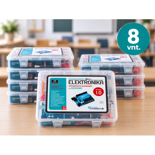
Smart Circuits with Arduino - 8 pcs, advanced class set
Ex Tax: 536.36€
Smart Circuits with Arduino - 8 pcs. educational set, designed to get acquainted with electronics, programming and Arduino in the classroom.
Arduino - a programmable electronic board that allows you to control lights, sensors, motors, displays and other components and create real-life projects. The set includes 17 step-by-step practical projects - from the first working LED to controlling sensors, motors, an LCD screen or creating a reaction game. All the electronic parts needed for the projects are included.
FOR THE STUDENT
- Learning through practice and experimentation
- Clearly visible programming result – the code controls real components
- Tasks consecutively become more complicated, so it's easy to get started
- The opportunity to apply knowledge when creating your own electronics projects
FOR THE TEACHER
- 17 prepared practical tasks
- Clear diagrams, instructions and explanations
- All the parts needed for the tasks in one set
- A comprehensive educational book in Lithuanian. The book contains information, step-by-step instructions, and diagrams presented in a vivid and clear language. Download the book.
Arduino microcontroller usage options:
GRND - 01. Getting Started – Blinking LED
Getting to Know You With Arduino, perform a very simple experiment called Blinking LED. During this experiment, Arduino should greet us by blinking an LED.
GRND - 02. Turning Knobs – Potentiometers
In this experiment, a potentiometer is tested. Potentiometers are usually used to adjust parameters such as volume or brightness. You will learn how to use a potentiometer to control the brightness of an LED with Arduino. The program demonstrates the operation of an analog input. Changing the position of the potentiometer knob will also change the LED blinking frequency..
GRND - 03. Colored light - RGB LED
A tri-color LED can glow in all the colors of the rainbow! Of course, this is much more interesting than a blinking LED. Actually, a tri-color LED is three LEDs (red, green and blue) in one housing. When we set various parameters for the brightness and intensity of the color on the Arduino digital output, we get new colors.
GRND - 04. Dancing LEDs - More LEDs
It's time to complicate the circuit a bit and connect as many as eight LEDs to the Arduino. Also, using Arduino, various lighting effects will be created. We will tell the eight LEDs to dance. The circuit is quite large and interesting. In this experiment, you will start creating your own programs and understand how Arduino works.
GRND - 05. Pressing buttons - Buttons
So far, we have done everything only with outputs. Now we are going to look at it from the other side and "play" with the inputs. In this experiment, we will use buttons as a sensor. This is the simplest and most obvious way to show how the Arduino can receive information. Our condition is that if any of the buttons is pressed, the LED will light up, but if both buttons are pressed, the LED will not light up.
GRND - 06. When light falls on it - Photoresistor
In the second lesson, you learned how a potentiometer works, the resistance of which varies depending on the rotation of the handle - the stem. Now you will learn to use a photoresistor, a semiconductor device, as a sensor that changes its resistance depending on how much light falls on its surface. Using a photoresistor as a light sensor, we will control the brightness of the LED.
GRND - 07. Let's measure temperature - TMP35 Sensor
We will learn how to use a temperature sensor with Arduino. We will set the Arduino IDE debug window to display temperature changes. Using the "port display" (Serial Monitor), we will read the temperature sensor readings. TMP35 is a simple temperature sensor that changes its output voltage in proportion to the ambient temperature. They can be used for all kinds of automation tasks where temperature-dependent parameter changes are necessary. Transferring information from Arduino to computers is an even more interesting topic than previous experiments - we will start using the Arduino serial port. So far, we have limited ourselves to using simple diodes to display any changes. We will make sure that Arduino can not only signal changes in the environment, but, if necessary, easily communicate with a computer and display all types of text and data on any terminal.
GRND - 08. Turning a corner - Servo mechanism
Servo mechanism, abbreviated "servo" - a motor consisting of an electronic circuit with feedback. The "Servo.h" library has been created for Arduino, which can work with various types of servo motors. Servo motors are ideal for electronics and automation - they are characterized by high speed and are able to accurately determine the desired position, which is not possible with conventional motors. They are quite easy to control, using variable pulse duration. In this experiment, you will learn how to use PWM (pulse width modulation) to control a servo motor.
GRND - 09. When music plays - Piezo Buzzer
Once again, we will try to bridge the gap between the digital and analog worlds. We will use a piezo buzzer, which produces a small "click" when we briefly touch its contacts to a 5-volt power supply. Try it! Of course, this is not very interesting, but if you apply voltage and immediately remove it, and do so at a speed of 100 times per second, the buzzer will start beeping. When hundreds of strings of tones are put together, music will play! GRND - 10. Musical synthesizer - Connecting a potentiometer Let's create a piezo synthesizer. We can use a piezo buzzer to generate sounds. It converts electrical frequencies into sound waves. Different sound waves are produced by quickly turning a voltage (pulse) on and off. The program text processes two parameters that are read from two potentiometers. One potentiometer sets the pitch level, the other sets the duration of the repeating cycle. GRND - 11. Turning a motor - Transistor and motor Earlier, we got acquainted with the servo motor that we controlled with Arduino? Now we will look at the rotation of a DC motor. This will require a transistor that can commutate, that is, switch (the transistor acts as a switch) a much larger current than the Arduino. When using a transistor, you need to make sure that its parameters are suitable for a particular equipment. The transistor that we will use in this circuit – TIP120, can handle a voltage of 60 V and a current of 200 mA, which is perfect for our motor!
GRND - 12. Let's turn on a larger load – Relays
Now we will learn to control relays, giving Arduino more power! Rather, we will teach Arduino to control a relay. A relay is an electrically operated, mechanical switch. Inside the plastic case is a powerful electromagnet. When it receives a charge, the relay is triggered - the armature is attracted by the electromagnet and the contact group connects or disconnects the load power circuit.
GRND - 13. More jumping LEDs - Shift register 74HC595
Finally, we have reached integrated circuits (ICs). Now, using the shift register integrated circuit, we will control 8 outputs using only three Arduino pins. The 74HC595 shift register is an integrated circuit that has eight digital outputs. To use them, we will use a new interface called SPI (serial peripheral interface), which we will use to transfer data to the Arduino. One shift register will add an additional 8 outputs to the Arduino and will occupy only three of its pins. We can connect a lot of such circuits. As a result, we will get a lot of additional pins, occupying the same three Arduino pins.
GRND - 14. Reborn Figures - 8x8 LED Module
In our next project, we will use a 64-LED matrix module as a display.
Since these modules use the MAX7219 integrated circuit as a controller, we will be able to turn each of the 64 LEDs on and off using only 3 pins of our Arduino. This is a simple and cheap way to control 64 LEDs and create a variety of animations. In addition, we can connect several modules together and thus control even more LEDs. Our program will use the LedControl library. Download and upload it to the Arduino IDE: C:\Program Files (x86)\Arduino\libraries folder. Then restart the IDE software. Create more animations using the generator: http://www.pial.net/tools/.
GRND - 15. Let's count - 7-segment indicator
The main advantage of LEDs is that, being small in size, some of them can be combined into one small and compact package and form what is commonly called a 7-segment display. A 7-segment display consists of seven LEDs arranged in a rectangle in the appropriate order (see below). Each of the seven LEDs is called a segment. Different combinations of the seven segments turned on and off allow you to display numeric values from 0 to 9. The location and pins (PINs) of each segment are marked with letters from A to G (see below). 7-segment LED displays come in two types: common anode and common cathode. The display with the number 5101AS printed on the side is a common cathode type display.
GRND - 16. Hello World - LCD Display
In this tutorial, we will learn how to connect an LCD to an Arduino and display all the data on it. A Liquid Crystal Display (LCD) is a complex electronic module that can be used to display text or numeric data. The display is built into a PCB. It has two lines of 16 characters each and a backlight for use in the dark. We used a Serial Monitor. You will see its similarity to an LCD and you will see that a large computer is not necessary.
GRND - 17. Playing - Reaction Game
Now that we have completed all the projects and learned all the basic terms of controlling components with Arduino, it is time to create something interesting. This circuit will show you how to create your own Simon Says game. With Arduino UNO, using LEDs, buttons, a buzzer, and a few resistors, you can create this and other interesting games. How does it work? When we upload the code, the buzzer will beep several times and all four LEDs will start flashing. The game will start when we press any of the four buttons. Then a random LED will flash. You will need to quickly press the button associated with that color LED, thus repeating the pattern. If the guess is successful, the pattern will be repeated again, only this time with another random LED added to it. The player must follow the pattern for as long as possible. With each successfully guessed pattern, an additional level of complexity will be added to the basic pattern.
Projects in the kit:
- GETTING STARTED - an introduction to how everything works.
- TURNING KNOBS - how to use a potentiometer to control the brightness of an LED with the help of Arduino.
- COLORED LIGHT - tri-color diodes, how to get new colors.
- DANCE LED – we will add more LEDs and make them dance with Arduino.
- WE PRESS BUTTONS – we will use the simplest sensor to transmit information to Arduino.
- WHEN LIGHT IS ON – using a photoresistor as a light sensor, we will control the brightness of the LED.
- WE MEASURE TEMPERATURE – we will use a temperature sensor with Arduino.
- WE TURN AN ANGLE – we will turn a servo using PWM (pulse-width modulation).
- WHEN MUSIC IS PLAYING – we will create melodies and we will play them.
- MUSICAL SYNTHESIZER – we will connect a potentiometer to the buzzer and create cosmic sounds.
- LET'S RUN THE MOTOR – we will use a transistor to turn the motor.
- LET'S TURN ON A BIGGER LOAD – we will control relays.
- MORE DANCE LEDS – using a shift register integrated circuit, we will control 8 outputs using only three Arduino pins.
- REGENERATING FIGURES – we will create various figures using an 8x8 LED module.
- LET'S COUNT – when you need to output numbers.
- HELLO WORLD – we will connect the LCD to the Arduino and display all the data on it.
- LET'S PLAY – a reaction game when we connect everything into one.
Set contents:
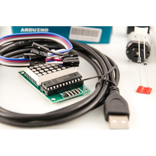
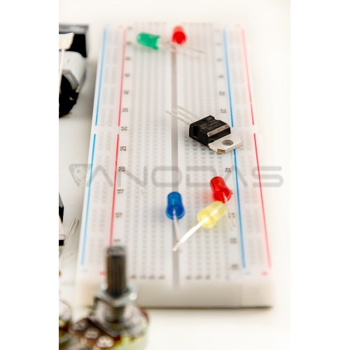
10x 220R resistor; 10x 1K resistor; 10x 10K resistor; 1x Potentiometer 10k; 2x Potentiometer 50k; 5x Red LEDs; 5x Yellow LEDs; 5x Green LEDs; 5x Blue LEDs; 1x RGB diode; 2x 1N4004 diode; 1x TIP120 NPN type transistor; 1x LM35 Temperature sensor; 3x Photoresistor; 4x Buttons; | 1x Mini-servo motor; 1x Buzzer; 1x DC electric motor; 1x Relay DPDT 5V-12A/125VAC; 1x 74HC59 shift register circuit; 2x 1-digit 7-segment module; 1x MAX7219 8x8 matrix module; 1x 16x2 LCD display; 1x Goldpin 1x40pin 2.54mm; 1x Arduino UNO R3 microcontroller; 1x Maxi breadboard (750 pcs.); 1x Breadboard wires (70 pcs.); 1x USB cable 1.8m; 1x Box;
|
Claim orders from Stores
You can claim your purchased items within 1 - 4 work days after making an order (if product is in local warehouse).
Please wait for an email notification regarding Your order status update.
Vilnius Store address: Vytenio g. 20, LT-03229 Vilnius, Lietuva
Kaunas Store address: Pramonės pr. 4D, LT-51329, Kaunas, Lietuva
Local delivery in Lithuania
Purchased items are delivered locally through Venipak service. Depending on availability of items, orders are processed within 1-3 work days. Orders made until 1AM are shipped the same day.
Local delivery (1-4 w.d.) price for items of any size is through through courier service is 4.90€ (incl. VAT), if the amount of the shopping cart exceeds 150€ - delivery is free.
Local delivery price to Venipak parcel terminals (1-3w.d.) is 2.90€ incl. VAT, if the amount of the shopping cart exceeds 50€ - delivery is free.
Local delivery price to Omniva parcel terminals (1-3w.d.) is 3.90€ incl. VAT,if the amount of the shopping cart exceeds 70€ - delivery is free.
Payment on delivery (COD) +2.00€ (incl. VAT).
You can pay for the goods at the time of delivery to the courier in cash or by credit card. Payment to Omniva parcel terminals is only possible by bank card.
A separate delivery fee applies to oversized items, regardless of the amounts and conditions stated above.
International delivery pricing through courier service
International shipping prices depend on geographic location:
Latvia - 5.50€ (incl. VAT)
Estonia - 6.50€ (incl. VAT)
Paid orders of more than 150€ are shipped for free to Latvia and Estonia.
other countries - negiotiated individually.
International delivery pricing to Omniva/Venipak parcel terminals
Latvia - 6.00€ (incl. VAT)
Estonia - 8.50€ (incl. VAT)
Payments:
We accept payments via PayPal for orders over 20€.
